Basic drawing techniques
Topics in this section
- Snaps and alignments
Snap to grid, object, vertex - Geometric constraints
Parallel, perpendicular, tangent, aligned - Coordinates, Distances, and Angles
Draw at fixed coordinates, length, distance and angle - Zoom and pan
Adjust the current view
Snaps and Alignments
Snapping is a function that allows the precise positioning of objects and insertion points by having some points of the canvas or parts of objects attract the cursor. It behaves like a magnetic property that adjusts the cursor position when it is within a certain range. HighDesign provides automatic snap to grid nodes, object body, vertex, intersection, right-angle / tangent and alignments.
Snaps can be toggled on and off through the Snaps menu on the bottom-left hand side of the main window in the Input Bar. Snap options can also be displayed as a handy floating window available via the Window menu.
Snap Types
The Snap function is always highlighted by a different shape of the pointer and marked by a handle on the screen that correspond to the current snap condition. Depending on the current preferences, the type of snap can also be highlighted by an on-screen label and a sound.
The available snap options correspond to the following snap types:
- Snap to grid: the pointer snaps to grid intersections and its sub-divisions;
- Snap to endpoint or vertex;
- Snap to object: the pointer recognises a minimum distance from an object body;
- Snap to intersection: all intersections are interpreted as endpoints;
- Snap to right-angle: the pointer changes when the current segment intersects another one with a right angle;
- Snap to tangent: the pointer changes when the current line is tangent to a circle / arc;
- Snap to alignments: the pointer snaps to two temporary guides;
- Snap to Sub-Objects: allows to snap to the objects inside the instances of symbols inserted into the project and inside the Viewports inserted in Layouts.
Alignments
When the pointer snaps to one endpoint of an object, that location is stored as current origin of the temporary guides; the guides are displayed when the cursor is on the X-axis or Y-axis of that datum point.
The pointer also snaps to the intersection of the guides: the intersection is highlighted with one point and both the guides visible.

Furthermore, when you place the pointer over a segment, this function stores the angle of that segment displaying the corresponding parallel and orthogonal guides: when tracing the line, just place the pointer over one datum point of that segment (endpoints or midpoint) to display the alignment.
To temporarily disable the Snap to alignments, hold the “cmd” key (Mac) or “ctrl” (Windows).
Geometric constraints
The Drawing Constraint functions allow you to quickly draw items with some conditions, such as parallelism, defined angle or intersections. The Input Fields on the Input Bar allow you to enter the coordinates of drawing points and the geometric dimensions of the objects, like length and angle.
Constrained Directions
Linear or polygonal graphic objects such as lines and Poly-lines, rotated rectangles, hatches, arcs and ellipses by radius and diameter, dimensions and walls, can be drawn aligned with one of the Cartesian Axes or rotated by steps of 15 degrees: to do this, just press the Shift key while moving the pointer.
Constrained Parallel, Right-Angle and Aligned/Tangent
These three buttons on the Input Bar provide the Right-Angle and Parallel constraints and the Intersected condition.
Constrain Parallel (P) and Right-Angle (R)
These conditions can be activated anytime with any tool or editing function and will affect the direction of the current movement.
To activate the Right-Angle or Parallel condition:
- After the first click of the current operation you are performing, click the button corresponding to the desired condition or press its keyboard equivalent (P or R);
- Click the reference object, e.g. the line you want to draw perpendicular or parallel to (the mouse-cursor changes to a pointing hand when on a valid object);
- To cancel a condition, press the Esc key on the keyboard.
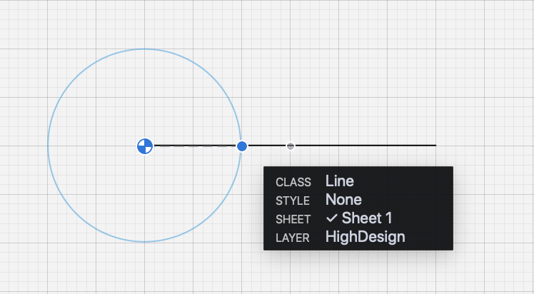
Constrain Aligned/Tangent
This condition constrains the pointer to intersect a reference line or circle, extending the line you are drawing to the intersection point, even outside the segment bounds, or constraining the direction to the tangent.
To activate this condition, click the button in the Input Bar or press its keyboard equivalent. If the condition is activated before the start point is defined, it constrains the start point to be aligned to the line or tangent to the circle. If activated after the first click, it constrains the end point.
The same result can be achieved by pressing the Command key + click on the datum line while drawing the line, polygon, wall or hatch/fill.
The Constrain Tangent option can be activated to construct a line tangent to an arc or circle, either from the starting point or to the end point.
To construct a line tangent to an arc or circle from the start point:
- Activate the Constrain Tangent option.
- Click on the reference arc or circle. As you move the pointer, the start point of the segment will keep the tangent condition that is closest to the clicked point.
To construct a line tangent to an arc or circle on the end point:
- Click to define the start point of the line.
- Activate the Constrain Tangent option.
- Click on the reference arc or circle.
The drawing constraints and the snap options can also be displayed as grouped in a floating window you can move to a convenient position on the screen. To show this option, select “Snaps” on the Window menu.
Coordinates, Distances, and Angles
The Input fields are grouped together in the middle of the Input Bar: use these fields to enter the values of constrained coordinates, length and angle of the object you are drawing. The X, Y and L fields also support additions of partial values.
When you click on one field or use the keyboard shortcut, a visual aid shows up to point the current constraint out.
In all input fields, values can be entered either as numbers, such as “100”, or as a sum of numbers, such as “100+20+60”.
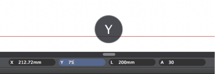
X and Y Coordinates
Coordinates in HighDesign are either absolute or relative. Absolute coordinates are calculated from the global origin point of the drawing, and relative coordinates are calculated from the previous point of the object.
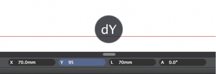
The insertion point of an object, that is its start point, is always set and viewed in absolute coordinates, with the X and Y values calculated from the origin of the current sheet. The next point is relative by default, but you can change it from relative to absolute by clicking the X or Y icon on the input field.
For example, in a line with points at (20, 20) and (100, 100), the end point is (100, 100) in absolute coordinates and (80, 80) in relative coordinates.
To set the absolute insertion point:
- Click on the corresponding input field or press the “X” or “Y” keys on the keyboard;
- Enter the desired X or Y distance from the Origin;
- Press Return to confirm.
To set the relative end point:
- Click on the coordinates fields or press the “X” or “Y” keys on the keyboard;
- Enter the desired dx or dy distance from the start point;
- Press Return to confirm.
You can change from relative to absolute coordinates and vice-versa by clicking the X or Y icon on the input field or using the corresponding key shortcuts.
Constrained Length
You can constrain a segment, line or radius to a fixed length after you have set the start point. In HighDesign, there are two methods for constraining a length that can be used interchangeably.
A. Define direction, set length.
- After the insertion point is set, move the pointer at the desired angle of the next point;
- Enter the desired length, either as a total length or as a sum of partial values;
- Press Return to confirm;
B. Define length, set direction.
- Click on the Length field or push the “L” key on the keyboard;
- Enter the desired length;
- Press Return to confirm;
- Move the pointer to set the angle of the vector.

Constrained Angle
To constrain the pointer movement to a fixed angle:
- Click on the “A” field (Angle) or push the “A” key on the keyboard;
- Enter the desired angle value (in degrees);
- Press Return to confirm;
- Move the pointer to set the desired length.
Relative Angle
It is possible to constrain the pointer to a relative angle to a reference direction:
- Click on the “A” field or push the “A” key on the keyboard;
- Enter the desired angle value (do not push the “Enter” key);
- Click on the reference direction (line, poly-line segment or wall);
- Move the pointer to set the destination length.
Constrained Distance
To set the distance of the insertion/start point of an object from a datum point, type the value, push Enter and click on the datum point; the distance is now displayed as a radius from the datum point: click to set the insertion/start point of the object.
Activate drawing constraints by using the TAB key
Drawing constraints for X and Y coordinates, Length and Angle can also be activated by pressing the Tab key on the keyboard. When you first push that key it activates the X constraint; then, in order, Y, L, A. Activating the Y constraint stores any values inserted into the X field, so to make it easier to set the coordinates of a point.
Zoom and Pan
These viewing tools, by default grouped in a handy dock on the border of the drawing area, are essential to handle drawings. The first time you launch HighDesign Panning, Zoom and Zoom to fit are docked as semi-transparent buttons on the top right corner of the drawing area: by right-clicking on the dock you can open a menu with the options to change the position of the dock.
Also, in the Zoom and Scrolling section of the Workspace pane of HighDesign Preferences you can open the “View controls” menu to change the position of the dock or to display the controls in the main toolbar.
Zoom
The Zoom tool allows you to enlarge or reduce the current view of the drawing by zooming in or out.
Click on the start point, then move the pointer and click again the define the rectangular area that will be zoomed. Hold down the Option key to zoom out.
The zoom factor is inversely proportional to the size of the zoom rectangle, that is, the smaller the rectangle is, the higher will be the factor.
Double-click the tool icon to set the view factor back to 100% (actual view).
Other zoom commands are grouped under the View menu, including “Zoom to Fit”, “Zoom In” and “Zoom Out”.
Dynamic zoom is enabled by pressing “cmd and +” or “cmd and -” buttons on the keyboard or, with a multi-button mouse, by rotating the wheel: rotate the wheel forward to zoom in and backward to zoom out. Trackpad gestures are also supported by the dynamic zoom.
Zoom to Fit
This viewing utility control is also available as a button in the dock of the viewing tools: by clicking this button the zoom factor and the center of the view are adjusted to fit the extents of the drawing area. This way you get a panoramic view of the whole visible drawing.
When one or more objects are selected this control centers the view of the selection only.
Pan
Use this tool to drag the drawing area and quickly move the current view. To use the Panning Tool click and drag the mouse pointer.
Double-click the tool icon to set the view to the center of the drawing.
The panning tool can also be temporarily activated with any tool by pressing the space bar on the keyboard: if you already started a task, for instance drawing a line, the use of the panning tool will not interfere with the current function.
With a multi-button mouse it is possible to pan the drawing by clicking the middle / wheel button and dragging the pointer.