Building Elements
Topics in this section
- Walls
Construct basic and compound walls with automatic connections - Columns
Insert columns and pillars - Windows
Add windows. - Doors
Insert doors of diverse families
Walls
The Wall tool allows the creation of walls which are parametric objects, automatically connected on their vertices and borders. To set the attributes, double-click the Wall Tool icon or select Edit ▸ Settings Window ▸ Wall… to open the Wall Settings dialog.
Walls are classified into two families: Standard-case Wall, made of one, uniform component, and Compound Wall, made of different components.
Standard-Case Walls
Standard-case walls have one uniform component and its representation can be a solid color fill, a hatch, or a combination of the two. The geometry can be rectangular, with a constant thickness from start to end point, or polygonal, with variable thickness from start to end.
Basic walls automatically join to other basic walls, regardless of thickness and fill, unless the joints are disabled in the Settings window.
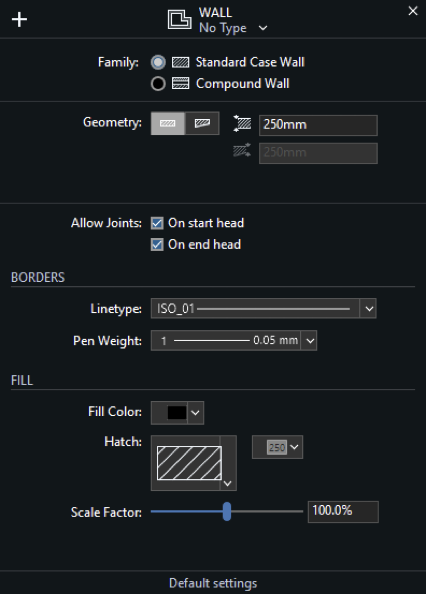
Standard-Case Wall Settings Window
- Type pop-up window and New Type icon.
- Family, Basic or Compound
- Geometry and Thickness, in the current unit: selecting the option of variable thickness enables the end thickness field.
- Leading side and Exterior side: select the construction side of the wall. You can also access this option by clicking the pop-up menu icon during the construction the wall. The option to invert the interior and exterior faces of the wall allows to switch the sides of the wall. The exterior side is highlighted in blue when drawing and selecting walls. Wall Joints options. Deselect an option to disable the automatic connection of new walls or to unlink an existing wall.
- Border attributes: Line type and pen weight.
- Fill attributes: solid color, hatch type and color, hatch scale.
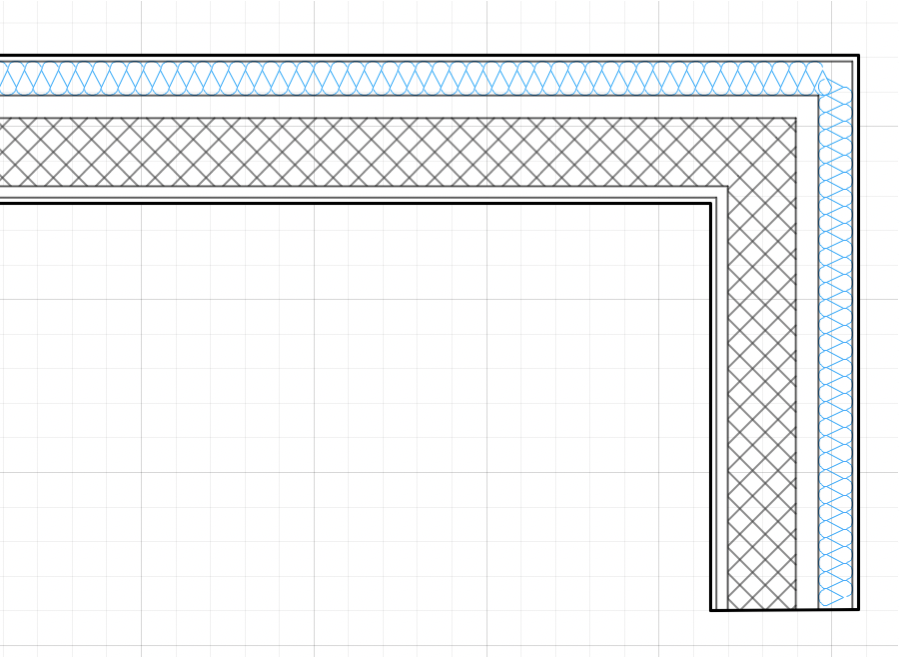
Compound Walls
Compound walls consist of multiple layered components, each with its own properties. Compound walls can only be rectangular in shape, with constant thickness from start to end. The total thickness is calculated as the sum of all the internal components.
- Compound walls can have any number of internal components, and you can add, remove, reorder and edit the components at any time through the Components window.
- By default, basic walls and compound walls do not join automatically, because they are different elements that would not be joined in a real situation. Also, they are made of different materials which would not match. However, if a particular situation requires it, you can choose to activate the Allow Joints options and attempt to join two walls of different type.
- Compound walls can use one pen weight for both borders and internal divisions, or you can assign a pen weight for the outer borders, and one for the internal components.
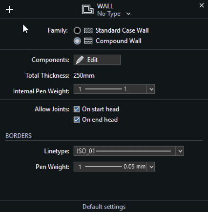
Compound Wall Settings Window
- Type pop-up window and New Type icon. This window lists all the available Types, of both basic and compound families. It is advisable to enter descriptive names when saving a new wall type.
- Wall Family.
- Components section:
- Edit Components button to access the Components window; use this button set the components of a new wall or edit an existing wall.
- Total computed thickness; the sum of thickness of the internal components determines the total thickness of the wall.
- Internal pen weight of components. The pen weight can be Same As Borders to set the same pen weight as that used for the borders of the wall, or one of the available pen weights.
- Leading Side: see Basic Wall Properties Window for the description.
- Wall Joints options: see Basic Wall Properties Window for the description.
- Border line type and pen weight. Internal components can only have a continuous line division.
Wall Components Window
Use this window to set and edit the components of a compound wall.
The table lists the components of the wall from the exterior side to the interior, with a progressive index number. The selected component is highlighted in the preview, which shows the current wall at the scale set in the lower left corner. You can check how the wall is rendered at the different drawing scales by using the drawing scale menu.
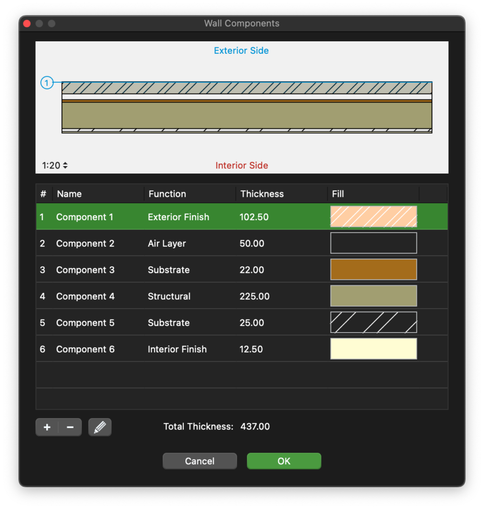
The total thickness of the wall is computed on the sum of the single components and shown at the bottom of the Thickness column.
You can add, remove and reorder the components, and rename a component by double- clicking its name. Use the + button to add a new component and the – button to remove the selected component in the table. Adding a new component opens immediately the properties editor. To edit a component, click the Edit icon on the right.
The properties of a wall component are:
- Function: each component has its own function which can define its behavior and appearance. The available functions are: Exterior and Interior Finish, Thermal Film, two kinds of Thermal Insulation, Air Layer, Substrate, Structural, Membrane. There can only be one exterior and one interior finish. The (batting) Thermal insulation component is always rendered with the Insulation line type.
- Thickness, in the current drawing units;
- Fill color, hatch, hatch color and hatch scale.
Click the Cancel ✖ or OK ✔ buttons to cancel or confirm the changes to a component and return to the list of components. The + button confirms the current component and creates a new one.
Construct and Edit Walls
To draw a wall, click to set its start point, move the cursor and click again to set its endpoint: walls are connected like poly-lines. Walls have their construction side and the “Exterior side” property, marked with a blue line, to consider when inserting openings: to change the leading side while drawing, click on the Option menu close to the last vertex. Press the Alt key to invert the exterior side while moving the cursor.
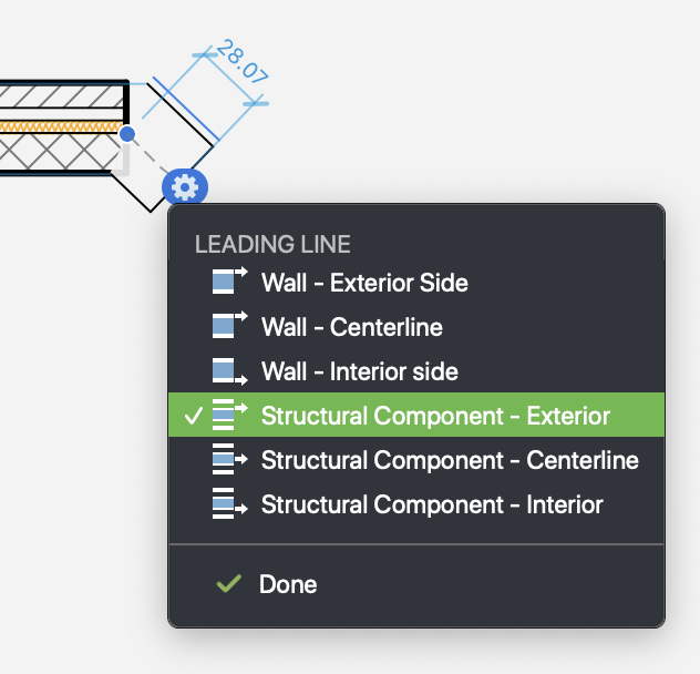
A compound wall can be inserted by its structural component: choose between exterior, interior sides and middle line to easily align your walls to the structural grid.
To edit a wall, select it and move, stretch, shorten it with the Arrow tool or change its parameters numerically via the Object Info panel.
Edit a Wall with the Object Info Panel
The Point section of the Object Info panel enables the changes of the coordinates of the three control points of the selected wall: use the arrows to select the active point and the fields to enter the new coordinates.
The Geometry section displays the following options:
- Length and Width fields to change its geometry;
- Leading side buttons to change the construction axis of the wall (this option can shift the selected wall accordingly);
- Invert Sides to invert Interior/Exterior side of the wall (this can invert the opening direction of windows and doors inserted in the selected wall).
The ID section shows the wall Name, Tag and Description fields to add information to the selected wall and provides the Settings button to open the Wall Settings window.
The Tools menu and the contextual menu provide two commands specific for walls: Convert to Wall and Rebuild Wall.
Convert to Wall
Convert To Wall applies to lines, polygons, arcs and curves. This function converts those objects into walls with the current settings: select the items to convert and then choose Tools ▸ Walls ▸ Convert To Wall on the Tools menu. This command is also available as a button in the Edit Tool Bar.
Rebuild Wall
Use this command to regenerate the geometry, side intersections and nodes of one or more walls. This is especially useful in situations in which a node needs to fixed.
The Rebuild Wall tool can either be applied to selected walls, or to multiple walls in one run by clicking on them.
To use it on the selection:
- Select the walls you want to rebuild;
- Choose Tools ▸ Rebuild Wall or open the radial menu and choose Rebuild Wall from
the Tools submenu.
To apply it to multiple walls:
- Choose Tools ▸ Rebuild Wall or open the radial menu and choose Rebuild Wall from the Tools submenu.
- Click once on each wall to rebuild
- Click on a void part or on another object to end.
Columns
The Columns tool is used to design square, rectangular or circular pillars.
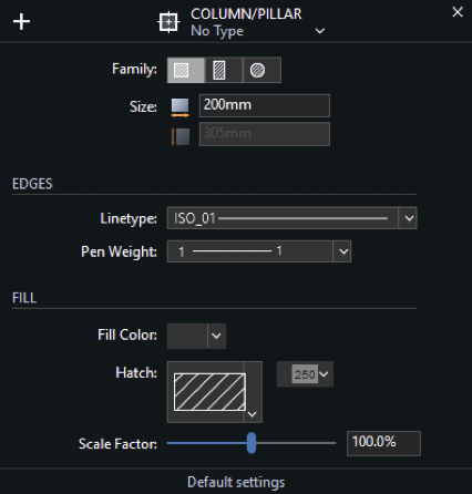
To use the Columns and Pillars tool, double click the tool icon and open the Settings window to choose the family of pillar. The Settings window displays on the top bar the option to open the pop-up window and select existing Types: it is also possible to save the current settings as a new Column Type.
Insert and Edit Columns in the Project
Set the base and click once to place the square pillar. As pillars can have any base angle, you have to click again to set the desired angle.
When the Rectangular pillars option is active, the input fields for width and height are both enabled.
Round columns require just to enter the diameter and one click for insertion.
The Column tool also features automatic alignment and distances. When inserting or editing a column, it automatically aligns to the structural grid of the previously inserted columns. You can also enter the dimension and automatically snap all the new columns to that predefined value.
Editing a Column with the Object Info Panel
Use the Point section to change the position of the column by editing the coordinates of its control points.
The Geometry section shows the Width, Height and Angle fields to change size and direction of the selected pillar or the diameter of the selected round column.
The ID section enables the addition of information (name, tag and description) to the selection.
Windows
The Windows tool allows you to design parametric openings to insert within existing walls. Even though windows are complete objects, they always refer to a wall and cannot be inserted outside a wall; furthermore, windows refer to the exterior side of the wall.
Window Settings Dialog
To edit and set properties and parameters of windows, select Edit ▸ Settings Window ▸ Window… to open the Window Settings dialog. This dialog provides all the options to customize the opening by choosing the opening family and all the parameters that can be stored as Window Types. The Settings dialog is structured as a two panes window: Geometry and Options.
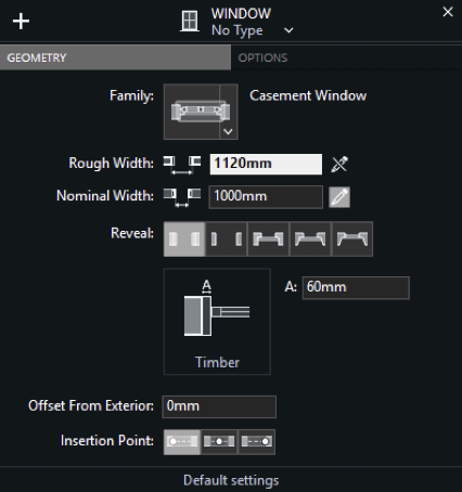
Geometry Pane
- Type pop-up and New Type icon: load a saved type or save a new type with the current settings;
- Family menu: click to choose the kind of opening. Available options are:
- Empty Opening
- Generic Window
- Simple Window
- Casement Window
- Single/Double-Hung WindowSliding Window
- Widths:
- Rough Width is the full extent of the opening in the structure of the wall, including the casing;
- Nominal Width is the span between the jambs;
- Reveal: select the shape of either side surface of the window, including jambs;
- Reveal Preview and settings fields: enter the desired dimensions;
- Offset from exterior surface of the wall: enter the value in the current units;
- Insertion Point: click to select the insertion point of the window (start, middle, end).
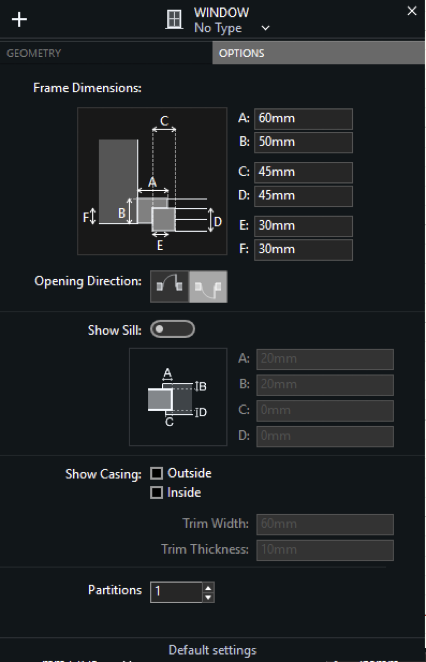
Options Pane
- Frame Dimensions: Preview and setting fields to enter the frame dimensions;
- Open Direction: select to flip the opening side (inside/outside);
- Show Sill option and input fields to set the offsets of interior and exterior sides and their dimensions;
- Show Casing options (Outside and/or Outside), Trim Width and Trim Thickness fields;
- Partitions: set the number of the vertical partitions of the window.
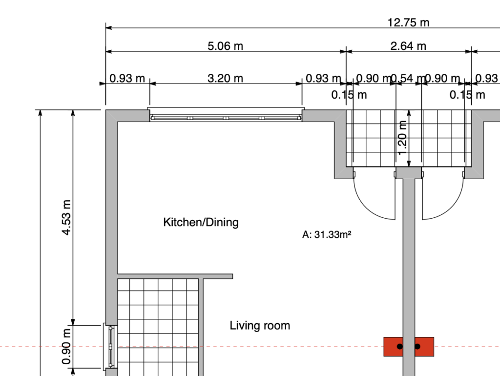
Insert a Window in the Wall
To insert a window in a wall, activate the Window tool in the Tools bar and do as following:
- In the Settings window load the Type if available or select the family of the opening;
- Enter the desired window settings;
- In the Project window set the position of the opening by clicking on the wall;
- Click the internal / external area of the wall to choose the opening direction.
As you move the cursor over a wall, temporary dimensions show the relative distances of the opening from the surrounding vertices or joints of the wall.
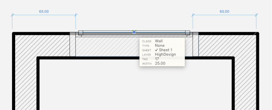
To set and constrain the value of either dimension, so that the opening is exactly at that distance from a reference point, enter the value on the keyboard and move the pointer, so as to choose which dimension on either side of the wall the value applies to. Click to confirm and insert the opening.
NOTE Windows are always inserted relative to the external surface of the wall, which is marked in blue when selected.
Editing a Window
Click one of the control points of the selected window and drag to resize or move it within the wall. If you drag the window by its center point you can enter the distance of the shift from the original center: the window will result shifted by the selected direction and distance within the wall.
If you drag the window by its vertices it will result resized by the new length value and according to the the direction of the shift.
Editing a Window with the Object Info Panel
The Geometry section displays the Rough Width and Nominal Width fields to change the size of the selected window.
The ID section shows the Name, Tag and Description fields to edit or add information to the selected window: use the Settings button to open the Window Settings dialog.
The Opening Direction of a window can be changed through the Settings window: select the window, open the Options pane of Settings and select Opening Direction > “Open Inside” or “Open Outside”.
Doors
As it is for windows, doors are parametric objects created through the Door design tool: these objects can be inserted within existing walls only and, for some of their parameters, doors depend on the walls they refer to.
Doors Settings Dialog
To open the properties and parameters setup window of doors, select Edit ▸ Settings Window ▸ Door…: load the existing Door Type if available or customize the door by selecting its family and setting all the parameters and options. Current settings can be saved as new types by pushing the Add icon.
The Door Settings dialog shows up with two panes: Geometry and Options.
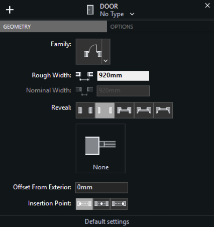
Geometry Pane
The Geometry pane offers the same choices of the windows Settings dialog. The Family menu displays a wide range of available door configurations:
- Empty Opening;
- Simple Door / Double Simple Door;
- Swinging Door / Double Swinging Door;
- Bypass Sliding Door;
- Surface Sliding Door / Double Surface Sliding Door;
- Pocket Door / Double Pocket Door;
- Folding Door / Double Folding Door.
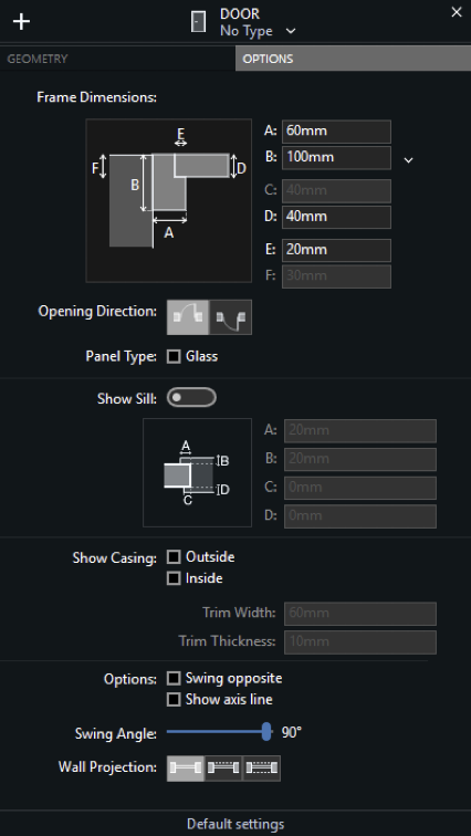
Options Pane
- Frame Dimensions: Preview and setting fields to enter the frame dimensions;
- Open Direction: select to flip the opening direction (inside/outside);
- Panel Type: option to represent the panels of the door as glass panels;
- Show Sill option and input fields to set the offsets of interior and exterior sides and their dimensions;
- Show Casing options (Outside and/or Outside), Trim Width and Trim Thickness fields;
- Options to invert the swinging side and to draw the axis line;
- Swing angle slider;
- Wall Projection options: click to project one, both or none wall edges.
Inserting a Door in the Wall
To insert a door in the project follow the steps below:
- In the Settings window load the Type if available or select the family of the opening;
- Enter the desired door settings;
- In the Project window set the position of the opening by clicking on the wall;
- Click the internal / external area of the wall to choose the opening direction;
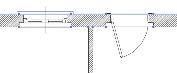
- For single doors (swinging, sliding, pocket or folding doors) click on the wall to position the door, then click in the desired quarter of the region described by the cartesian axes to set its opening or swinging side. As you move the cursor over a wall, temporary dimensions show the relative distances of the door from the surrounding vertices or joints of the wall. As for windows, to set and constrain the value of either dimension, so that the opening is exactly at that distance from a reference point, enter the value on the keyboard and move the pointer, so as to choose which dimension on either side of the wall the value applies to. Click to confirm and insert the opening.
Editing a Door
Drag the selected door by its vertices to resize it or by its center point to move it within the wall.
Edit a Door with the Object Info Panel
The Geometry section displays the Rough Width and Nominal Width fields to change the size of the selected door.
The ID section shows the Name, Tag and Description fields to edit or add information to the selected door: use the Settings button to open the Door Settings window for specific editing options.