The structure of a HighDesign project
Topics in this section
- Layers
Setting up the layers used in the project. - The Project Browser (SE/Pro)
Using the Project Browser panel. - Drafting Sheets (SE/Pro)
What is a drafting sheet and how to use its properties. - Trace References (Pro)
Display another sheet for tracing and reference. - Details (Pro)
Add detail areas to create detailed views of your drawings. - Layouts (Pro)
Use layouts to present the project.
A project is a complex set of drawings, symbols, views, details and documentation elements such as annotations, tags, dimensions and non graphic information. All these elements need to be organized and arranged in a convenient way. Layers, Drafting Sheets and Details allow to manage the project effectively.
Layers
A layer is a concept used in CAD and design programs to conveniently group elements in a logical way. As its name implies, this concept derives from the use of overlaid semitransparent papers in manual drafting. As in manual drafting, layers are used in HighDesign to organize a complex drawing into different component parts, but, differently from real layers, each CAD layer has its own properties.
Decomposing a drawing into its components is one of the most important operations in computer design. Any object, even the most complex, can only be analyzed by separating its elements in logical groups, applying criteria that depend on the object nature and on the designer goal.
Any element of a drawing in HighDesign belongs to a layer: there is no restriction on what types of objects you can assign to a layer. You are free to group different elements together in the most convenient way to you or according to the drawing standard you are following.
HighDesign layers have the following properties:
- Name. Layers are identified by their name;
- Visibility. A layer can be visible or invisible. Items belonging to a visible layer are redrawn to screen, are printable and selectable; invisible layers are not printed.
- Lock. Layers can be locked to make their items not selectable.
- Color. Layers can have a default 32 bit color. If the byLayer option is on (you can change it by opening the “Colors” pop-up menu in the Properties bar and selecting “byLayer”), any new item gets the color of its layer.
- Opacity. Controls the overall opacity at which the objects on that layer are displayed.
- Drawing tool binding. You can create a binding between a drawing tool and a layer so that, every time you activate that tool, the layer is set automatically. To enable this option, click the corresponding check box. The Tool column on the main table will become active. Click the icon on a row to select a tool or method to associate with that layer.
Quick Layer Management
The layers of the project are listed on the Layers menu of the Properties Bar: select the desired layer by a click to update the current default or to change the layer of the selection.
The name of the current layer or of the layer of the selection is shown on the menu.
- The Layers menu displays the main functions to manage layers: you can switch to other layers, show or hide layers, lock some layers and access the Layers Manager to create and arrange new layers.
- The commands on the upper section of the menu allow to create new layers, open the Layers pane of the Resource Manager window and switch layer masking on and off.
- You can mask the layers of a project so that only the current layer is visible and editable. Masking is a switch on/off command, and as long as the mask is active, changing the current layer will automatically hide the other layers. Once masking is switched off, the other layers return to the original visibility they had before the command.
- Layers are document based and are only available to the project you created them for.
- In addition to the pop-up menu, you can manage project layers with the Layers panel, available under the Window menu, or with the Resource Manager.
The Project Browser (SE/Pro)
The Project Browser shows a logical hierarchy for all the Drafting Sheets of the project and also lists Details and Layouts which are special sheets used to present the project. By using this panel you can quickly create, rename and delete sheets, change their visibility, protection, optional size and scale attributes.
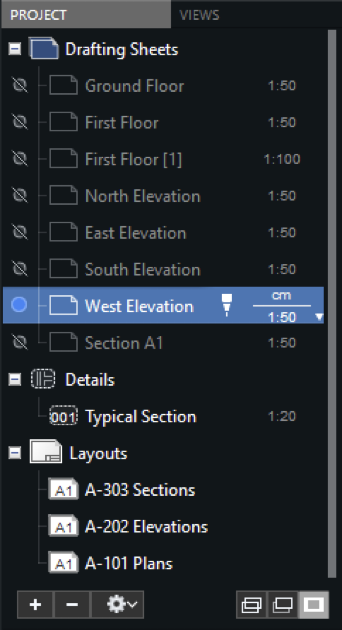
To create a new sheet, click the New Sheet button (+) and modify its name. By default, new sheets are created with the current drawing scale and units. You can change the units and scale of a sheet by double-clicking it on this window.
To arrange a sheet, drag it to the new position: the table order corresponds to the actual display order, where the topmost visible sheet is the first item of the list.
You can control how the sheets are displayed on screen by clicking the Opacity button. There are three states: all sheets equally visible, the current sheet displayed normally and the others dimmed, or only the current sheet visible.
Utility Buttons
The Project Browser panel provides several buttons on the footer of the window to quickly access functions and set options.
- New sheet: adds a new sheet at the top of the list; new sheets have a default progressive name which can be changed by double-click.
- Delete selected sheet: all objects of the current sheet can be moved to another one or deleted.
- Action menu. The action menu lists the commands to manage sheets as in the Project menu, apart from those specific to the selected objects of the drawing, and the commands to change the visibility status of all sheets in relation to the current one.
- Display modes: All Visible, Dim Others, or Hide Others.
Drafting Sheets (SE/Pro)
A HighDesign project is made of different sheets, each with its own page size, drawing scale and units, depending on the part of the project it represents. HighDesign provides an intuitive way of managing projects by introducing the concept of “Drafting Sheets.”
A drafting sheet is a space where you can freely draw at any scale and units, without particular constraints. You can use a drafting sheet to lay out a sketch of the project, insert a DWG/DXF drawing or a picture, create a structural grid, draw a component of the product, a symbol, or a full detailed drawing.
Each sheet in a project can have its own drawing scale. Measures and dimensions must be entered in their natural, real-world scale and are automatically adjusted to the current scale. Annotative objects, like texts, annotations and dimensions are entered at their 1:1 scale.
- A Drafting Sheet in HighDesign has special attributes such as visibility, write-protection, etc., that make it a convenient way of organizing a project: you can, for instance, put a different drawing on each sheet or use a sheet for the main drawing and draw sections on additional sheets.
- A HighDesign project, either for architecture, engineering or design, is thus made up of several drawings contained in a single document.
- The ability to show or hide sheets, transparency and write protection allows you to compose a complex project even in a single layout.
These are some of the properties and advantages that sheets provide:
- Independent drawing scale and optional paper size of the current sheet;
- Independent drawing units;
- Write protection and display mode (visible, hidden and dimmed);
- You can search and select items on a single sheet or on all sheets;
- Visible sheets can be merged into one;
- You can create and delete any number of sheets;
- The print functions only prints the visible sheets;
- A sheet can be saved as a new document;
- Sheets can be reordered and renamed; two or more sheets can share the same name;
Drafting Sheets are managed through the Project Browser Panel of the Sidebar and via the Project menu, which provide all the commands to create, rename, delete and reorder sheets, move and duplicate items across sheets, show and hide, etc.
Drafting Sheet Properties
Drafting sheets have adjustable properties that control their behaviour and look and can be modified both via the Project Browser panel and the Object Info “Drafting Sheet” panel. The Object Info panel shows all the sheet properties while the Project Browser only shows the most commonly accessed properties, such as visibility, name, scale, etc.
You can also open the “Drafting Sheet” info panel by double-clicking the sheet’s icon on the Project Browser.
New sheets automatically inherit the default page size and units set in the Project Settings window.
- Name: you can enter any sheet name without particular restrictions.
- Visibility: a drafting sheet can be visible or hidden. Hidden sheets are not computed in the general drawing bounds and do not intercept the snap options. Click the icon to change the visibility.
- Write protection: this option locks the sheet. Objects on a locked sheet cannot be selected and modified.
- Drawing Scale:
- To change a drawing scale, enter the scale ratio (e.g. “1:200″) or click the popup arrow to open the menu of predefined scale. When using imperial units, it is possible to switch the scale representation between ratio and verbal (e.g. 1” = 1′) by clicking the icon on the Drawing Scale popup menu.
- It is also possible to enter a scale value below 1.0, such as 2:1.
- The scale of a sheet can also be changed via the Sheet Scale dialog, available from the Scale popup menu or from the menu item Drawing > Sheet Scale. This dialog provides the ability to define the origin point for the scaling operation and options to apply the scale to the current sheet only, to the visible sheets or all drafting sheets.
- Units:
- Linear units
- Angular units
- Area units
- Paper Size:
- Drafting sheets can have no page limits (“paperless”) or show a page size.
- Use the Standard menu to choose a size standard system and click on the preview to select the desired page.
- Show or hide the margins of the page. Margins are set in Project Settings > Paper Format.
- Tracing Reference: another sheet that is displayed below the current sheet’s content. You can change its opacity, angle and colour effect. See the next section to learn more about tracing references.
Trace References (Pro)
Introduced in v. 2022.2
A trace reference is a view of another sheet that is displayed under the current sheet’s contents and that can be used to trace parts of that drawing onto the current sheet, or to mark points and references to draw a new component, a floor plan, an elevation or a cross section view.
Trace references can only be activated on drafting sheets and cannot be exported to PDF. They can be printed and exported as image.
To activate a trace reference use any of the following methods:
- From the menu bar, choose View > Trace Reference > Activate Reference;
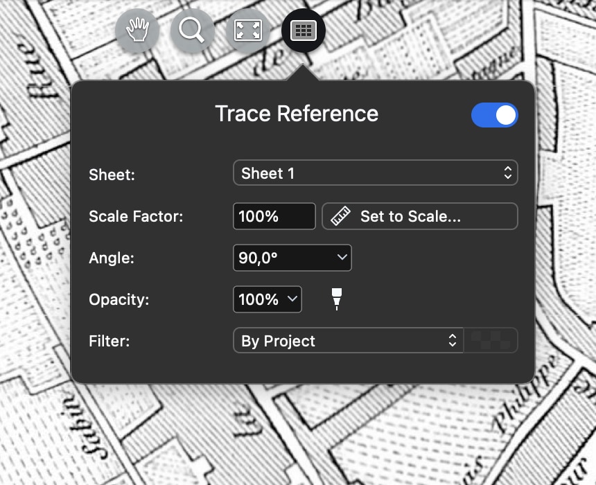
- If the on-screen View buttons are visible, click the Trace Reference button and push the switch;
- Click the switch on the Trace Reference section of the Object Info panel. The same switch can be used to show or hide temporarily the tracing reference of the sheet.
Next, choose a source sheet from the Sheet menu. Only the eligible sheets are listed.
When you select a sheet, its content is displayed on the current sheet at its original location. The current sheet now acts as the host sheet. The size of the referenced drawing is automatically adjusted to match the scale of the host sheet. Once inserted, you can change the opacity, enable or disable the snap to the referenced drawing, move, rotate or crop the reference as needed.
- The Trace Reference panel provides the Opacity slider to change the opacity of the referenced drawing to any value between 0 (completely transparent) to 100 (completely opaque).
- Use the Angle slider to rotate the drawing. The center of the rotation is always the center of the drawing.
- The trace reference can also be displayed using any of the built-in colour effects: choose the desired effect from the Filters menu. Trace references and viewports include special filters that can automatically hide all texts and annotations in the referenced drawing.
- To move or crop the trace reference, it must be selected first. To select a trace reference, move the pointer near its border and click it.
Scaling a Trace Reference
By default, a trace reference is displayed at the same drawing scale as the host sheet. By using the Scale Factor options it is also possible to change the size of the displayed drawing by a custom factor. You can do that in two ways:
A. Enter a percent value in the Scale Factor field.
The reference is scaled around its center by the specified amount. Although you can enter any valid number larger than 0, it is useful to remember that images in the drawing cannot be resized above 32765 pixels per side. If you need to enlarge a picture by a very large percent value, it is important to review the scale of the source sheet where it was inserted and change it to a more fitting value.
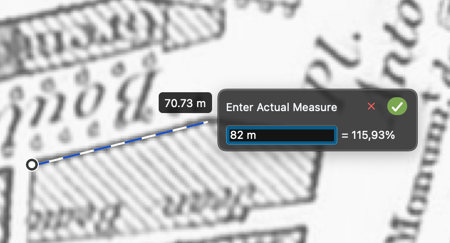
B. Trace an element in the drawing and enter its real size.
The Set to Scale command allows you to resize the reference by tracing a line on the referenced drawing and entering its real length. The drawing will be resized so that the traced line matches the specified length.
Activate this method by pushing the “Set to Scale” button, then:
- Specify the first point of the line.
- Specify the second point of the line.
- Enter its real length and push the Confirm button or press Return.
Scaling a trace reference through the Scale Factor commands only applies to the trace reference and does not affect any drawing object added to the host sheet.
Moving a Trace Reference
You can move the trace reference anywhere on the sheet. To begin the operation, select the trace reference by clicking its border and move the pointer inside the drawing. The cursor changes to indicate that it is possible to move the drawing: click anywhere to begin the Move operation.
You can place the drawing wherever it is more convenient to you. Click again to end the Move command. If you later need to restore the drawing to its default position, use the command Reset to Default Position from the View > Trace Reference menu.
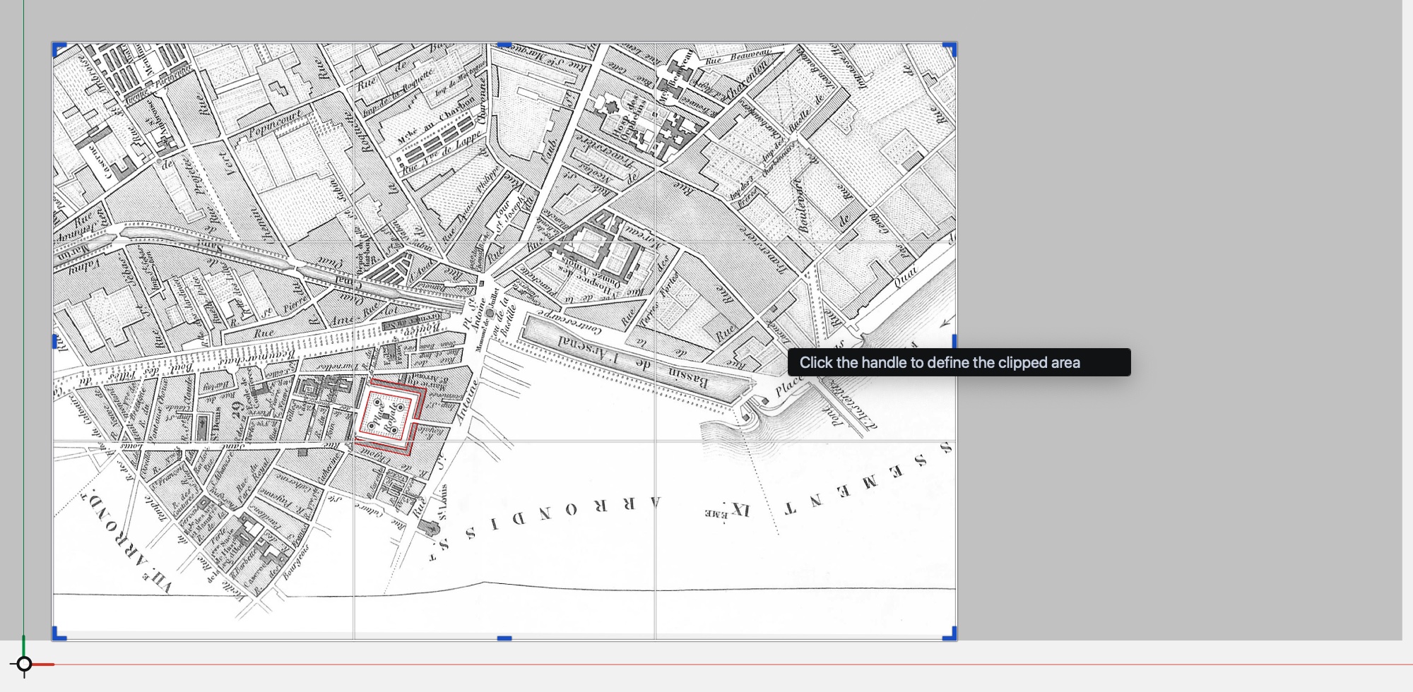
Cropping a Trace Reference
When it is not necessary to view the entire drawing contained in the referenced sheet, it is possible to crop, or clip, the visible drawing to a smaller rectangle.
To crop a trace reference, select it by clicking its border and click any of the handles that appear at the corners and on the sides of the box. You can then resize the crop area as needed. When cropped, a trace reference only displays what is inside the crop area. To adjust the crop area so that it shows a smaller region or a different part of the drawing, select the reference and use the crop handles. When the cursor is near the borders of a selected reference that has been cropped, a gray overlay shows the full extents of the source sheet.
Moving, rotating and resizing a trace reference does not modify the source sheet and only the displayed view is transformed. You can undo and redo any transformation operation at any time.
Details (Pro)
Detail Sheets are specialized drafting sheets used to add detailed views of the project. This class of sheets allows a better organization of the project by separating the drawing sheets, where the project is, from the other drawings that complement the main design. Details are typically “extracted” from a larger design and include additional elements and information, usually at a larger scale.
There are two methods for creating a detail sheet: by detail area and as an independent detail.
To create a detail sheet by a detail area:
- Go to the drafting sheet where the desired drawing is and create a detail area on the part of the drawing from which the detail is going to be generated.
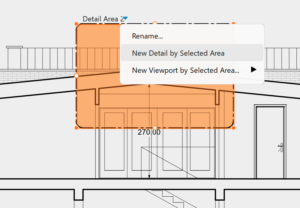
- Select the detail area, click the drop-down triangle next to the area’s title and choose New Detail by Selected Area.
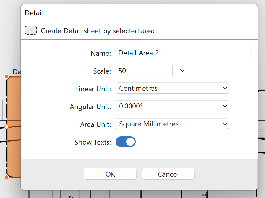
- In the dialog, enter the name of the detail sheet and define its scale and units. The Show Texts switch controls the visibility of texts, dimensions and other annotations in the detail. All these options can also be set later in the Object Info panel.
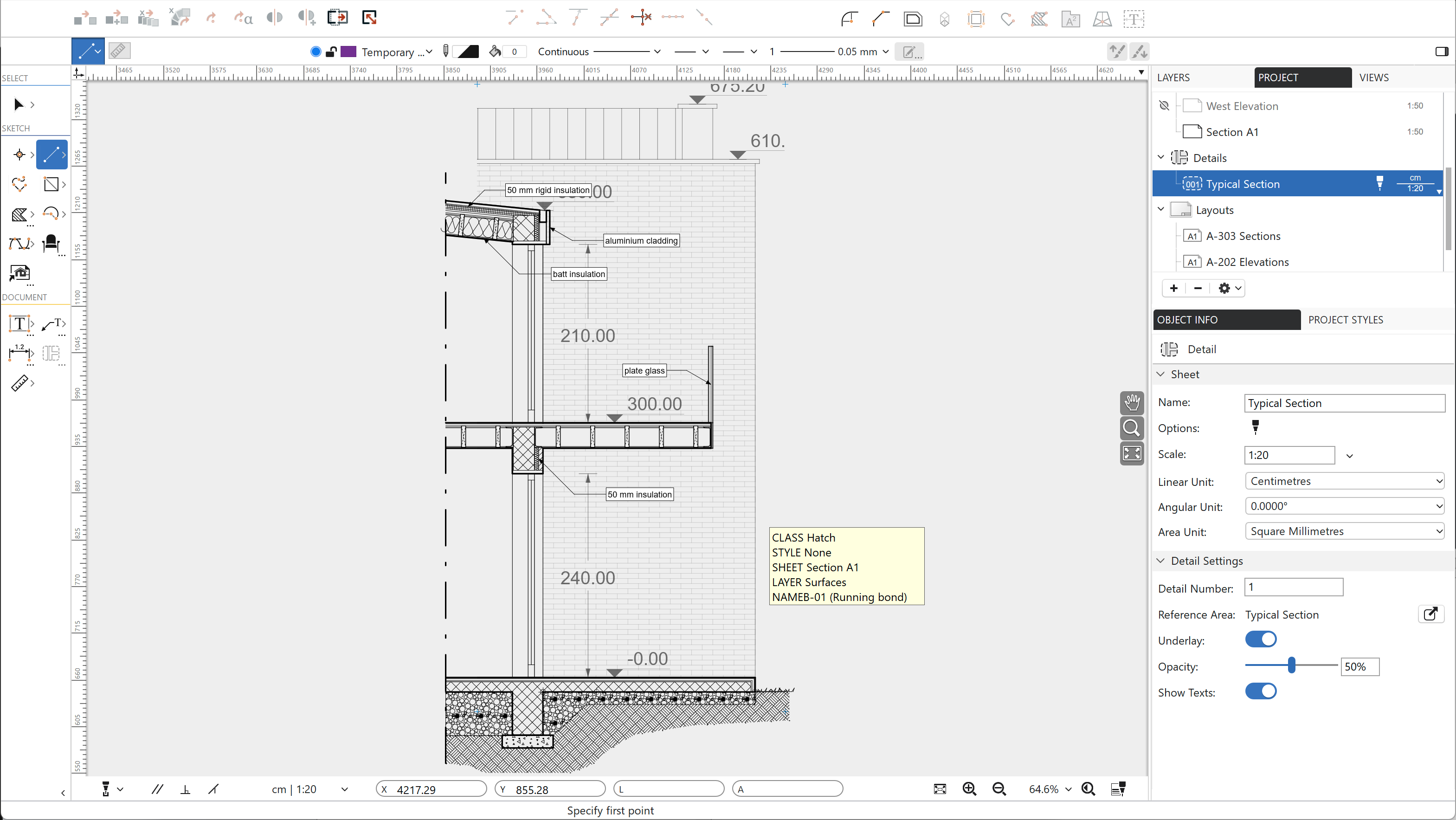
The new detail sheet by default shows the drawing contained in the source area. This is called “underlay” and it can be toggled on and off and displayed at the desired opacity. The underlay serves as a reference for further drawing and automatically updates whenever the original drawing is changed. The objects that are visible on the underlay can be snapped, but cannot be selected.
To create a new detail sheet as an independent detail:
- On the Project Browser, click the plus (+) icon on the Details group heading or choose Project > New Independent Detail…
- Define the sheet’s properties in the pop-up dialog.
- Independent details are not linked to a detail area and show no underlay.
Detail sheets support a sub-set of the drawing tools: you can use sketching and documentation tools, but design tools as Walls or Windows are not available.
In linked details, the underlay can be exploded and turned into a group for editing and further transformations: to explode the underlay use the menu item Project > Explode Underlay.
The Object Info panel provides the main information and the options of the current Detail. Details do not have the Paper Size option. To add a detail to a layout, create a viewport on the layout and choose the detail as source sheet for that viewport.
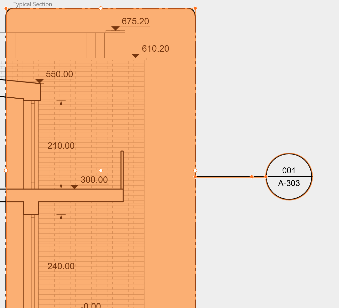
Once a detail area is linked to a detail sheet, it becomes a Callout. Callouts have an additional marker that contains information about the detail:
- the upper half shows the identification number of the linked detail sheet.
- the lower half shows the layout identification number where that detail has been placed as a viewport.
When the detail area is selected, you can click either of the labels in the callout mark to go directly to the linked sheet.
Further information about detail areas is available on the chapter Annotate the Project.
Layouts (Pro)
Layouts are special sheets used to display the various drawings of the project. Think of layouts as the presentation sheets that are going to be published and shown to the client.
Layouts are always at 1:1 scale, can contain their own drawings and annotations, such as tables and text blocks, and can display drawings taken from the main design inside scaled windows called viewports.
By using layouts, you can separate the model, that is the actual project you are working on, from its representation. More information about layouts is at the chapter Present the Project with Layouts.