The advanced modules of Photogrammetry, image editing and drawing presentation
Topics in this section
- Photogrammetry
Straighten pictures and create their vector projection. - Image editing
Edit brightness, contrast, colors, etc. - Drawing Presentation
Create high-impact images of your drawings.
Photogrammetry
HighDesign Pro provides a powerful, single-image photogrammetry tool to obtain the actual projection of the architectonic elements captured in a picture: this function can be used for surveys of architectural façades and any planar surface and it only needs a normal camera and two measures. No specific equipment nor knowledge is required.
Photogrammetry in HighDesign offers two tool methods:
- Image Correction: transforms the original image by rectifying the perspective deformation
- Perspective Tracing: creates a corrected projection by tracing the elements in the image after the internal geometry of the image has been set up. All projections are vector-based.
The following are some requirements and suggestions to obtain the best results:
- The image must include at least two horizontal and two vertical items (e.g. a door, a window, wall bricks) and, if available but not strictly required, two items with the third dimension. These requirements are the only really needed to use the photogrammetry tool in HighDesign.
- If possible, avoid too angled views because the projection could be deformed on the edges of the image;
- For the same reason as above, avoid fisheye lenses (<28 mm);
- The image should include at least one horizontal and one vertical dimension; however, if you do not have those dimension, you can set up the projection with any dimension and later resize the resulting drawing.
As a rule of thumb, make sure the image includes some reference items and it has not been clipped or deformed. When the third direction (depth) is not available, the internal geometry of the view relies on the diagonals of the picture’s rectangle, hence the importance of preserving the original shape of the picture.
Set the Required Data
The setup process is very simple and it does not require any specific knowledge.
To start a photogrammetry, select Tools ▸ Photogrammetry. HighDesign switches to the Photogrammetry workspace, with the Photogrammetry setup window, a gray background and a limited set of drawing tools:
- Arrow;
- Construction objects;
- Lines;
- Poly-lines with straight segments;
- Hatches;
- Curves;
- Viewing tools (Panning, Zoom and Measure).
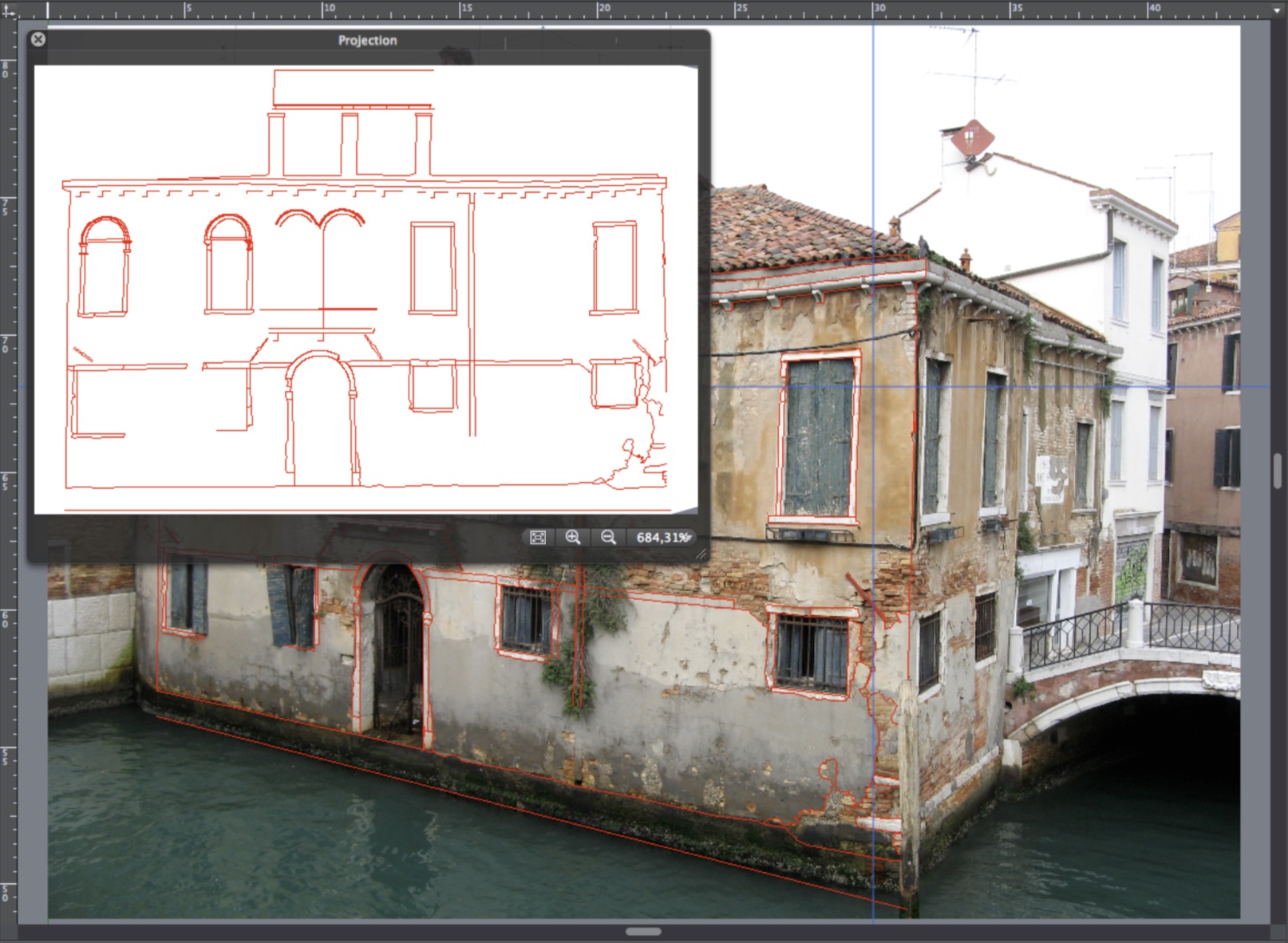
STEP 1: select the image
Push the “Choose…” button and select the image file to open. Supported file types are: TIFF, PNG, JPEG.
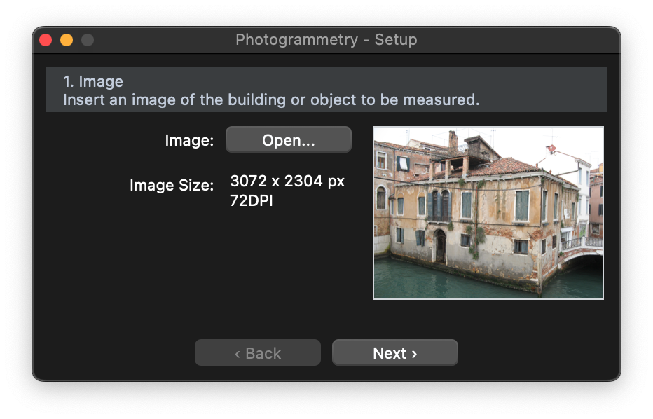
Press the “Next” button: the image is now displayed on screen and the Photogrammetry setup window changes.
STEP 2: define the internal geometry
Once the image is open, select the geometric type of the object in the picture. There are two possible options, based on the visible geometry and camera angle:
- All three directions X, Y and Z are visible in the image: there are at least two horizontal lines, two vertical and two for the depth;
- Two directions X, Y are visible. The image shows at least two horizontal lines and two vertical, but no depth line is visible; this type includes pictures taken with the lens parallel to the surface and scans of plans.
When you choose the geometry type, a grid is added to the image on the drawing area. Adjust the grid to match the shape of the object in the picture.
Click the handles of the grid on its vertices and move them until they match the horizontal and vertical cue lines that are visible in the picture. Windows, side walls, sills, jambs of doors and windows and frames are all useful elements.
If the geometry shows two sides of the object, a second grid serves for the reconstruction of the third direction. Drag the two blue depth lines by their endpoints to match the depth cue lines on the picture. You can adjust the grid and the depth lines keeping in mind that usually lines far from the center of the picture have a deformation depending on the quality and focal length of the used lens.
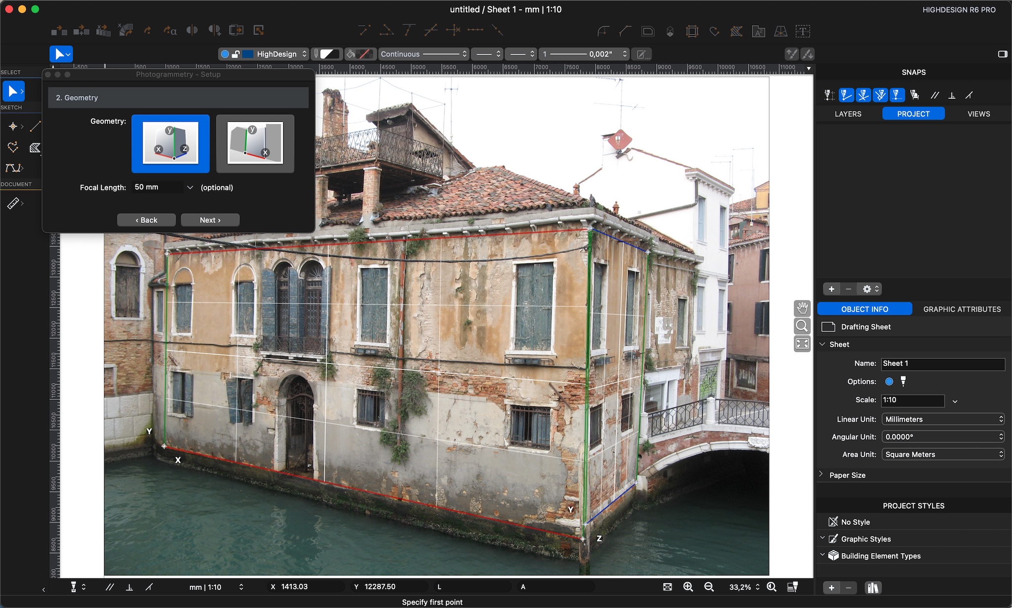
- The focal length value is optional.
Push “Next” button to go to the next step of setup.
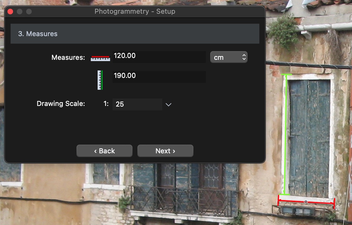
STEP 3: define the known measures
Two lines, one green vertical and one red horizontal, are displayed over the picture. These lines, drawn in the perspectival view corresponding with the internal geometry of the picture, will be utilized to enter the two known measures.
- Drag the vertical line over the known dimension, in this case the jamb of the arched door, and stretch/shorten it by the endpoints till it matches the known object: enter the known vertical measure in the corresponding field of the setup floating window and select the drawing units.
- Drag the horizontal line over the known object, the sill of the door, adjust it till it matches the known dimension and enter the actual measure in the corresponding field and set the drawing scale of the projection.
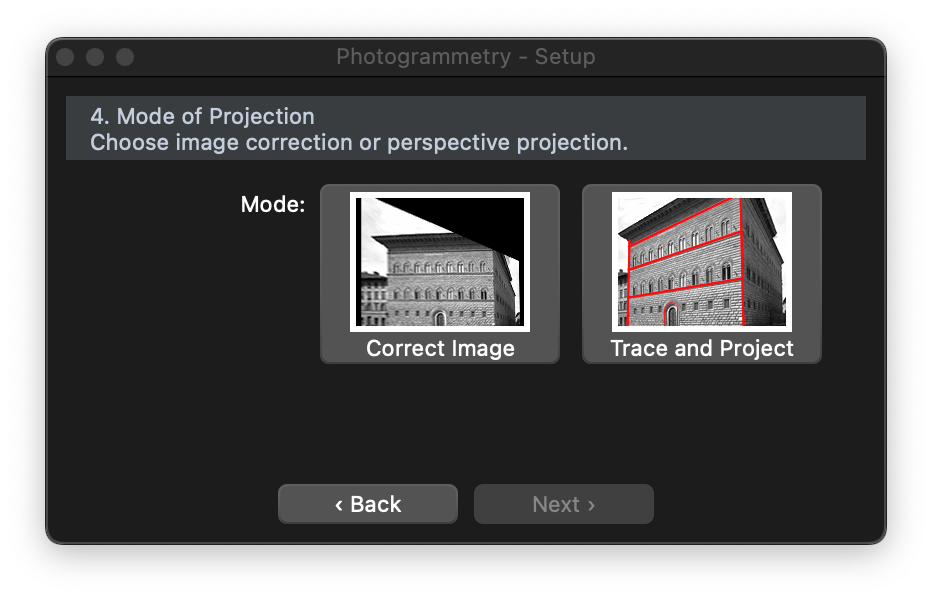
STEP 4: choose projection mode
The setup is now complete and it is possible to choose the mode of projection between image deformation and vector projection. By choosing the image deformation the image will be stretched to correct the perspective deformation and match the given proportions: the resulting image then could have to be resized to fit the known measures.
The second option, “Trace and Project”, consists in tracing all the objects of the image you wish to survey to get the projection at the desired drawing scale.
Draw and View Projected Items
As already mentioned, the workspace of the Photogrammetry tool provides a limited set of drawing tools and three Sheets are listed in the Sidebar: “Sheet 1”, the sheet created by default when you launch HighDesign; “Photogrammetry”, which stores the image and all the setup data and this is the sheet you use to trace all the objects to project; “Projection”, which is displayed as a floating window when you are on sheet “Photogrammetry”. Also, this workspace has the following characteristics:
- Directions are constrained to vanishing points; holding down the Shift key while drawing or tracing lines, the directions are constrained to the closer vanishing point, vertical or horizontal.
- The Projection window displays the result of all projections, that is, all the items drawn within the Photogrammetry environment are projected in real time at the drawing scale previously set.
The “Projection” sheet, as all drafting sheets, can be used to draw, edit, save and export the projection like a separate drawing.
Photogrammetry Utilities
The Tools menu includes some commands that are specific to the Photogrammetry workspace and allow you to manage some important functions:
- Photogrammetry: used to start a new photogrammetric projection or to resume the current one.
- Reset Photogrammetry: clears all settings (geometry and known dimensions) and brings the photogrammetry process back to the setup step; the setup window opens again and all projected items are removed. Please pay attention when using this command as it’s not undoable.
- Exit Photogrammetry: hides the picture from the project and pauses the Photogrammetry environment switching the workspace to Project. Items drawn to the current sheet are not deleted; select “Photogrammetry” to resume the photogrammetry.
Edit Images
HighDesign lets you insert images into a project and treat them as any other vector object. The Edit Image tool (Tools menu) lets you edit and crop the image, enhance and adjust the values of brightness, contrast and saturation.
It often happens to have the need to adjust the brightness, contrast, levels of color of an image to be used for a photogrammetric projection or as a background for a drawing: HighDesign provides an integrated image editing module to quickly apply many image enhancements.
To edit an image, select it and choose Tools ▸ Adjust Image: a window opens with all the controls to edit the selected image.
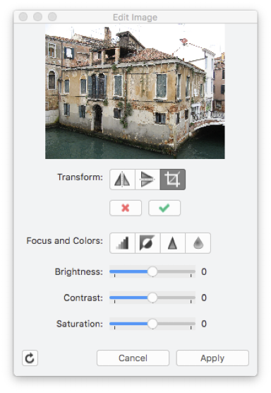
The Adjust Image dialog shows the preview of the image on the top. The controls are grouped as transformation buttons, advanced filters buttons and the sliders for brightness, contrast and saturation. The available options are:
- Transform:
- Mirror Horizontal, mirrors the image horizontally on its Y axis;
- Mirror Vertical, mirrors the image vertically on its X axis;
- Crop, trims the borders of the image leaving the selected area only;
- Focus and Colors:
- Grayscale, changes all colors to gray;
- Invert, inverts all colors from positive to negative and vice versa;
- Sharpen, enhances the contrast on the edges;
- Blur, smoothes the image;
- Brightness, controls the amount of light in the image;
- Contrast, adjusts the contrast between colors;
- Saturation, enhances the color saturation.
To apply a filter, push the corresponding button or move the slider. Sharpen and blur filters can be applied multiple times. Any filter you apply, which you can preview in the thumbnail, is stored in a temporary image until you push the “Apply” button, which applies all filters in queue to the main image, while the “Cancel” button clears the filter queue.
The “Revert Image” button, on the lower left hand corner of the window, clears all applied filters from the image.
Drawing Presentation
This is a 2D rendering tool that creates high-quality images of your project with varying effects of background, pen and fill colors, border and margins, watermark and adjustable size and resolution.
This tool not only applies anti-aliasing to object edges, but it also allows customizable print size and image resolution and provides background options, frames and color effects to make high impact presentations of your projects. The result is an image that can be exported into any of the supported graphic file formats. To set all options, select Tools ▸ Render to open the image settings dialog.
Set Image Options
Use this dialog to set the visual effects and options to create an illustration.
- Image effects: click to show the graphic options.
- Border: option to display a border, color and thickness of the margin.
- Watermark: options to add a digital signature or watermark to the image.
- Image size: options to set the image resolution and size.
- Preview of the resulting image.
- Buttons to save the current settings as a new theme or to delete the selected theme.
- List of loaded themes.
Once all the settings are done, if you wish to save the current settings as a new theme for future use, just push the “+” button close to the themes menu to see it listed on the menu with the desired name. Click “Ok” to confirm and open a new window displaying the resulting image or “Cancel” to dismiss this dialog.
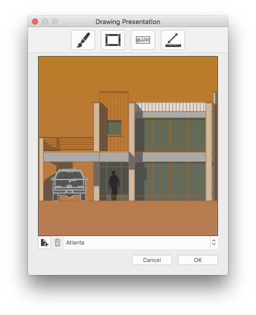
Image Effects
The options to apply graphic effects to the image include:
- Background:
- By Project: sets the background to the same color as used in the main project window;
- Plain Color: use the button to select the color;
- Horizontal Gradient: select left and right colors of the gradient;
- Vertical Gradient: select upper and lower colors of the gradient;
- Image, tiled: draws an image as background; pictures smaller than the destination image are tiled; select the image from disk;
- Image, resized: draws an image as background scaling it to fit the destination image. Images are scaled non-proportionally; select the image from disk.
- Drawing Color:
- By project: keeps the original colors of the drawing;
- Custom color: choose the color on the pop-up menu.
- Fill Color:
- None;
- By Project;
- Monochromatic: choose the color on the pop-up menu;
- Grayscale;
- Sepia.
- Line type: select the line type from the loaded list.
Watermark
The Watermark feature of the “Render” tool allows you to add a text watermark to the image: the text style options include Font, size, text style (bold, italic, underline) and color. Through a menu it is possible to set the position of the watermark within the image.
Image Size options
In this pane are grouped all the options to set the desired format, size and resolution of the resulting image.
- Preset: choose the size that best fits your needs from the many standard formats in the menu;
- Pixel Size: use the fields to enter your custom image size in pixels: click the icon to lock the desired ratio;
- Resolution: set a resolution of 72 dpi for Web publishing or presentations, whereas 300 dpi or higher resolutions are best for print output;
- Print Size: you can set width and height of the printout, using the menu on the right to set the units.
Export Images
The resulting image is displayed on a new window which provides some buttons, including the zoom buttons: press the “Save” button to export the image as a TIFF, PNG or JPEG file or the “Copy” button to copy the image to the clipboard.
You can also drag and drop the image on the main project window to insert it in the current sheet.